What’s New
This new CAMIO version demonstrates a strong development commitment and direction for the platform, with key new functionality and significant advances particularly for automated programming.
- Full support for the SLK20 VIVID CMM laser scanner.
- CW43L mode for the PHS2 probe head.
- Probe designer support for PH6M and additional star styli.
- Improved out-of-tolerance and min/max report labels.
- Additional fitting and filtering output.
- Properties view settings linked to tolerance window.
- Improved master sphere import.
- Improved sphere definition using CAD.
- New offset distance for sphere measurement.
- Improved error handling for probe errors.
- New GOPARK position DMIS command.
- Improved arc and line feature extraction from curves.
- New individual points output for profile tolerances.
- ISO GD&T concentricity tolerance with two datum features.
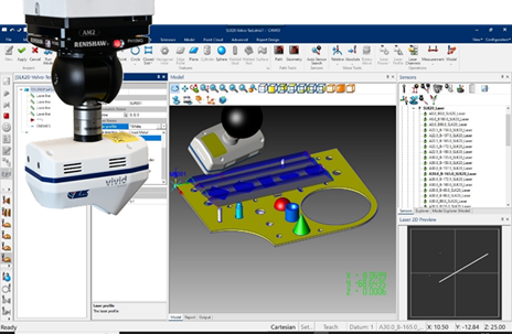
New SLK20 laser scanner support
First CAMIO release with full support for the SLK20 VIVID CMM laser scanner
- Freeform surface inspection
- Geometric feature measurement
- CAD based scan-path generation.
- Teach & Learn online programming
- Offline programming and simulation.
- Real-time 2D preview window.
- Multi-exposure scanner settings.
- Point cloud filtering and meshing.
- Laser calibration management.
- Automated probe change.
- CAMIO PCA (point cloud analysis).
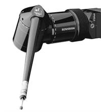
New CW43L mode for PHS2 probe head
- PHS2 probe heads can now be used in CW43L probe head mode.
- This new functionality allows an existing DMIS program for a CW43L probe head to be used with a PHS2 probe head.
- The PHS2 mimics the movements of the CW43L, using the CW43L A-angle as the PHS2 E-angle and the inverse of the CW43L B-angle as the PHS2 D-angle.
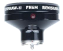
PH6M multi-wire fixed probe head
Probe Designer now supports the OH6M multi-wire probe head.
The PH6M autojoint probe is compatible with the SP25M scanning probe, as well as the complete Renishaw probe range using the PA series of probe mounting adaptors.

Improved Report Labels
Report Labels now support automatic background colours to highlight out-of-tolerance features.
The label background changes colour based on the most out-of-tolerance value of the reported feature.
The colour gradient uses the current Colour Bar Style and provides the option to configure the colours used.
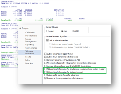
Additional Fitting and Filtering Output
New Tolerance Evaluation options support the output of additional comments, for features and patterns/simultaneous requirements, to the CSV and DMIS output files.
The additional output relates to the GEOALG command and point filtering for features measured using tactile scanning.
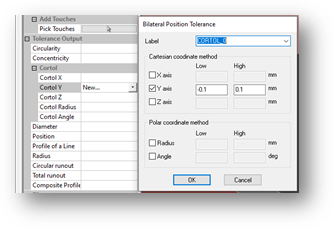
Properties View Linked Bilateral Position Tolerance
The Bilateral Position Tolerance window now defaults to the selected options when invoked from the Properties View.
Multiple options can also be selected and added to the Teach Path at the same time.
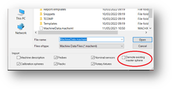
Improved Master Sphere Import
When importing a master sphere with a different name to the current master sphere, the option to make the imported or current master sphere a satellite sphere has been added.
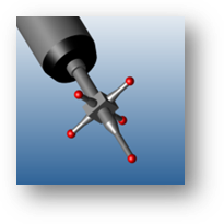
Additional Star Stylus Support
- Probe Designer now supports three more standard Renishaw star-styli.
- M2 4-way star, Ø0.5 mm ruby balls, 10 mm span.
- M2 4 ball star, Ø1 mm ruby balls, 10 mm span.
- M2 5-way star, Ø2 mm ruby balls, 18 mm span.
Improved DMIS Error Handling
Probe Not Armed Error: If error handling has a ‘Jump To’ line label set and a probe not armed error occurs, program execution will now move to the program line label specified.
New GOPARK Command
Support for ‘GOPARK’ has been added for the DMIS program. This new command provides DMIS level control of sending the CMM to define park position.
Improved Feature Construction
The construction window now includes the number of measured points for each feature. The Point Buffer option, for selecting all measure points, can now be applied to a group for selected features.
New Sphere Measurement Offset
A measurement offset distance can now be applied to spheres measured using a touch probe or scanning probe.
The offset distance is applied relative to the equator and pole of the sphere, as defined by the sphere direction. The measurement strategy paths are distributed evenly, with the first path at the offset distance from the equator.
Improved Arc and Line Extraction
For more accurate and reliable feature extraction from curves, the XTRACT command has been improved with new search parameters.
New ‘Line radial search size’ and ‘Line tangency search size’ search parameters when extracting Lines from Curves.
New ‘Arc radial search size’ and ‘Arc length search size’ search parameters when extracting Arcs from Curves.
Improved Profile Tolerance Output
Tolerance Evaluation has been improved with a new setting for reporting the individual points of a profile tolerance.
The new setting can be applied to plane, cylinder, cone and sphere features.
Improved ISO Concentricity Tolerance
Reporting concentricity using the ISO GD&T standard now allows the selection of up to two datum features. For example, the concentricity of a feature to a plane and a circle can now be reported.
Improved Report Min/Max Labels
Report Min/Max Labels are now distinguishable with the addition of ‘Min’ or ‘Max’ text, this is in addition to the feature name text currently.
Improved Sphere Definition
When defining a sphere in the CAD view, the sphere direction can now be set more easily using a mouse.
As the mouse is moved around the selected sphere, the sphere direction selection snaps to the closest axis of the current Part Coordinate System.