What’s New
- Improved Measurement Strategies and new streamlined workflow, resulting in greater productivity when programming.
- New default Measurement Strategy for point, circle, line, plane, edge, cylinder, slot and curve features.
- Copy a Measurement Strategy to quickly apply multiple measurement techniques to a feature.
- Probe Path simulation now displays the measurement mode, touch points, intermediate moves and connecting moves.
- New Clearance Planes automatically provide safe connecting moves between inspected features.
- Automatic arc-path intermediate moves to avoid probe collisions when measuring an external circular feature.
- The Report Summary, QIS label information and non-program related events can now be sent to Metrology Gate.
- The inspection program Run Number is now stored with the measurement results in the Inspection Database.
- Enhanced GD&T with Customised Datum Reference Frames for positional tolerances.
- Multiple bilateral position tolerances can now be created more efficiently in a single operation.
- Added support for unequally disposed tolerance bands according to the latest GD&T standards.
- The coordinates of taught GOTO moves can now be rounded using a user-defined number of decimal places.
Errors resulting from feature measurements, constructions and extractions can now be processed within the DMIS program.
Measurement Strategies
All measurement strategy tools have been moved to the Properties window to improve the speed and usability of CAMIO when programming features, touch points and paths.
For point, circle, line, plane, edge, cylinder, slot and curve features, a default measurement strategy is provided together with a list of strategies applicable to that feature. Measurement strategies can now be easily copied to save-time when programming a feature using multiple data collection techniques.

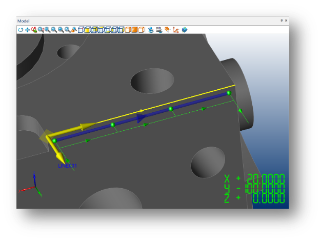
Path Probe Simulation
Probe Path simulation now displays the measurement mode, touch points, intermediate moves and connecting moves.
Different line styles and colours show the measurement mode of each feature (manual, program or automatic). The pre-measurement simulation of the probe path can be used to optimise the program sequence and avoid collisions when programming online or offline.
Clearance Planes
Clearance Planes provide safe passage of the probe and simplify programming – by automatically providing the connecting moves between one inspected feature and the next. After a feature has been measured, the probe uses the Clearance Plane to automatically move clear of the feature, and then to move safely around the part to the next feature to be measured.
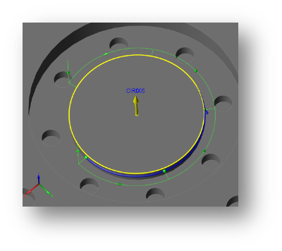
Intermediate Arc-moves
Automatic arc-path intermediate moves between touch points when measuring an external circular feature reduce the potential of a probe collision.
Previously when measuring an external circular feature the probe took a straight-line path between touch points. The new arc-path considers the feature diameter, stylus tip diameter and approach setting to ensure the probe takes a safe route around the feature between touch points.
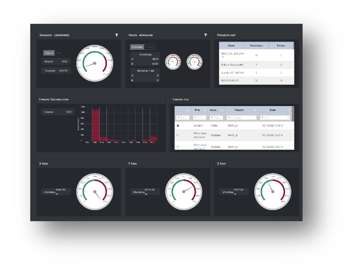
Metrology Gate
The inspection report summary, QIS label information and non-program events can now be sent to Metrology Gate.
The inspection report summary with details of the number of reported features in or out of tolerance, QIS labels (Quality Information System) for communicating associated quality information and the details of events that occur outside of running a program can now be sent to Metrology Gate.
Metrology Gate is an online portal with real-time monitoring for your quality data, CMM performance and environmental conditions. Data analysis for all your measuring machines and locations globally is provided using a single interface with user access provides 24/7 using any internet enabled device.

Inspection Program Run Number
The inspection program Run Number is now stored with the measurement results in the Inspection Database.
The Run Number is incremented each time the program is run. A permanent record of the number is now kept in the Inspection Database.
The Run Number can be used to identify a particular set of stored results and determine how many times the program has been executed.

Customised Datum Reference Frames
Enhanced GD&T with Customised Datum Reference Frames for positional tolerances.
Customised Datum Reference Frames provide a more precise definition of the Degrees of Constraint (DOC) controlled by each datum feature. True Position modifiers enable full customisation of the datum reference frame translation and rotation in all three axes, in accordance with ASME Y 14.5.
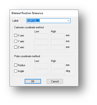
Bilateral Position Tolerances
Multiple bilateral position tolerances can be created more efficiently in a single operation. Checkboxes enable multiple axes, radius or angle tolerances to be define at the same time, resulting in a more efficient process and improved user experience.
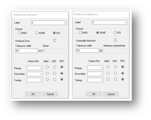
Tolerance Limits Or Band
Added support for unequally disposed tolerance bands according to the latest GD&T standards. In accordance with the latest ISO and ASME standards for tolerancing, users can now configure profile tolerances, for a line, surface and point, with unequally disposed upper and lower limits.
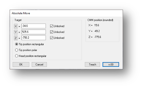
Rounded GOTO Moves
The coordinates of taught GOTO moves can now be rounded using a user-defined number of decimal places. The precision of intermediate and connecting moves is often less important when teaching programs. Reducing the number of decimal places used for the move coordinates makes the DMIS program easier to read.
Error Handling for Feature Evaluation
Errors resulting from feature measurements, constructions and extractions can now be processed within the DMIS program.
DMIS level error handling has been extended to Feature Evaluation, this enables any feature evaluation and construction error to be trapped at the program level. A Jump To command is used, with other high-level commands, to further process the error as needed.
Trapping and processing error messages at the DMIS program level further extends the automated inspection capability of CAMIO.